Business Box
This chapter shows an overview of the LEDs and connections on the router.
Structure and connections
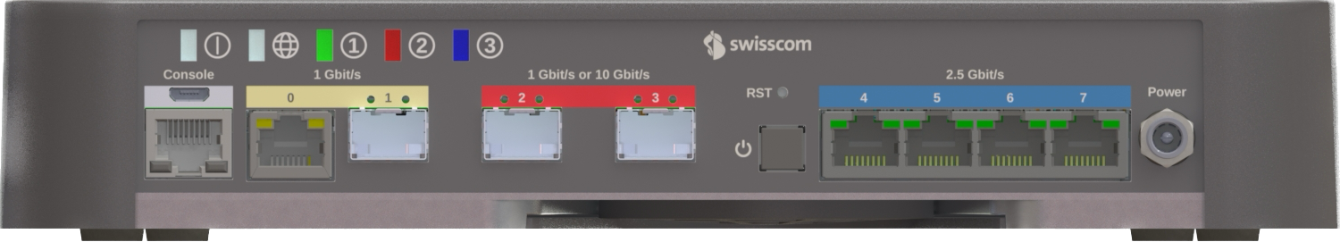
| Interface Number | Dashboard Label | Port Type | Usage |
|---|---|---|---|
| Console | Console | Serial console | Serial console interface |
| RST | - | Reset Button | Used to reset the router (less than 5s: reboot, more than 10s: factory reset). Resetting the router will interrupt services. Exercise caution when deciding to press this button. |
| 0 | GE0 | 1000BASE-T | WAN Interface used for Mobile Access, Mobile Backup or Application Based Routing (ABR) |
| 1 | GE1 | SFP | Port disabled and not in use |
| 2 | GE2 | SFP | WAN Interface for DSL, FTTH or FTTO connectivity |
| 3 | GE3 | SFP | Optical Layer 3 LAN Interface |
| 4 | 2.5GE4 | 2.5GBASE-T | Layer 2 LAN Interface |
| 5 | 2.5GE5 | 2.5GBASE-T | Layer 2 LAN Interface |
| 6 | 2.5GE6 | 2.5GBASE-T | Layer 2 LAN Interface |
| 7 | 2.5GE7 | 2.5GBASE-T | Layer 2 LAN Interface |
Description of the LEDs
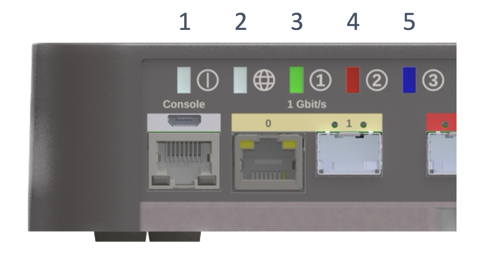
System status LED (LED 1)
| Color | Description |
|---|---|
| Solid White | The system is running properly |
| Slow Blinking Amber | The system is being powered-on or restarting |
| Solid Red | Error message that indicates severe Software issue |
| Fast Blinking Red/Amber | Error message that indicates severe Hardware defect |
| Solid Amber | System warning (e.g. abnormal CPU, memory usage, temperature too high, Fan) |
| Off | The system software is not running or is resetting |
WAN status (LED 2)
| Color | Description |
|---|---|
| White | The network service has been established |
| Red | The network service is unavailable (correct in case of Mobile Access) |
| Yellow | Layer 1 link up but network connectivity is unavailable |
Service status (LED 3, 4 & 5)
| Color | Description |
|---|---|
| White | No service provisioned |
| Red | Service not running |
| Green | Service running |