For EC-XL sites: Setup redundancy
Depending on the type of ordered EC-XL location, redundancy must be setup one of two ways:
-
Active-Active: In EC-XL with sync link, both WAN links are in an active-active mode, so data traffic is transmitted over both links. In order to enable this, both routers must be inter-connected via Ethernet links called sync links. Not only data synchronizing traffic is transmitted via the sync links, but also the data traffic of the customer runs over it. Besides the redundant router operation, this setup allows the usage of both WAN links to achieve higher bandwidths.
-
Active-Passive: In EC-XL without sync link, the WAN links are in an active-passive mode, so data traffic is transmitted only over one link at a time, while the other link acts as a backup. In this setup the routers do not have to be directly interconnected, allowing for more flexibility in the deployment.
Changing the configuration from sync-link to no-sync-link and back requires site reordering and repeated zero-touch provisioning (ZTP) of the routers.
Setup of EC-XL with sync link (active-active)
To conclude the installation and activate an EC-XL site with sync link, both routers have to be connected to each other. This achieves redundant router operation and guarantees high service availability for the EC-XL site.
The two routers are connected with two separate Ethernet connections. Each of these connections occupies two LAN ports. These cannot be used for anything else.
The following kinds of connection are available:
-
Direct router connection (recommended)
-
Router connection via switch
-
Router connection between two sites/locations
In the following sections, please select the type of connection you would like to use.
Depending on the router type, two optical or two copper cables are supplied for the EC-XL router connection. If the connection cannot be made with these cables and a house installation is required, you must commission an electrician of your choice to do this. The house installation is not carried out by Swisscom.
These two Ethernet connections between the routers may not fail simultaneously and must therefore be set up with high availability (redundant).
Direct router connection
In this kind of connection, both routers are directly connected with two of the Ethernet cables included in delivery.
Please select the corresponding router model below and connect the router as described.
This kind of direct router connection leaves two of the Ethernet cables from the EC-XL router delivery free, which are no longer needed for the installation.
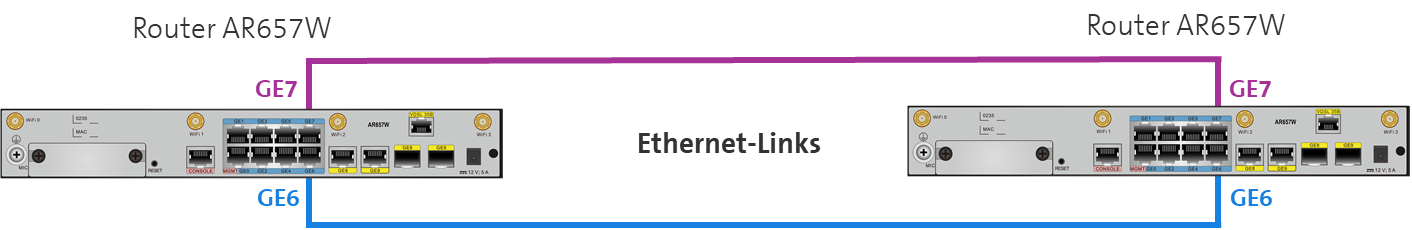
Router AR657W
For router model AR657W, connect Ethernet ports GE6 of both routers with one of the supplied Ethernet cables. Now also connect the ethernet ports GE7 of the two routers with the other ethernet cable supplied (Figure 28).
You can also use your own Ethernet cables. However, the length of your Ethernet cable must not exceed 100m (Ethernet standard). For longer connections, please use appropriate Ethernet switches.
When both connections are established, the LEDs GE6 and GE7 on the front of both routers must now flash.
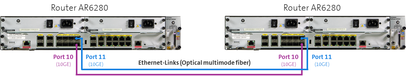
Router AR6280
For the router model AR 6280, first insert the two 10G SFP+ modules included in delivery per router into the 10GE ports 10 and 10GE ports 11. Then connect the 10GE ports 10 of the two routers with one of the optical fibre cables included in delivery. Now also connect the 10GE ports 11 of the two routers with the other optical fibre cable included in delivery.
Once both connections have been created, the LINK LEDs of the 10GE ports 10 and 10GE port 11 of both routers should now flash.
Router AR8140
For the AR8140 router model, first insert the two 10G SFP+ modules inculded in the delivery per router into the 10GE ports 6 and 10GE ports 7. Then connect the 10GE ports 6 of the two routers with one of the optical fibre cables included in delivery. Now connect the 10GE ports 7 of the two routers with the other optical fibre cable included in delivery.
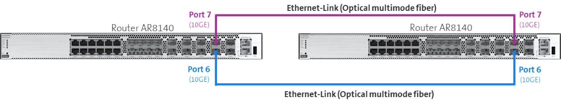
Instead of using the supplied multi mode SFP+ modules, it is also possible to setup the sync link using single mode SFP+ modules. These can be seperatly purchased through the Swisscom Extranet portal.
Router connection via switch
The Enterprise Connect Service only supports direct router connection. If the router connections have to be provided via a LAN infrastructure or another network, this is your responsibility. You are then also responsible for ensuring that the required availability of this connection is guaranteed and you take care of the operation of the infrastructure. Of course, Swisscom also offers additional services that support you in configuring your infrastructure.
Important information and conditions:
-
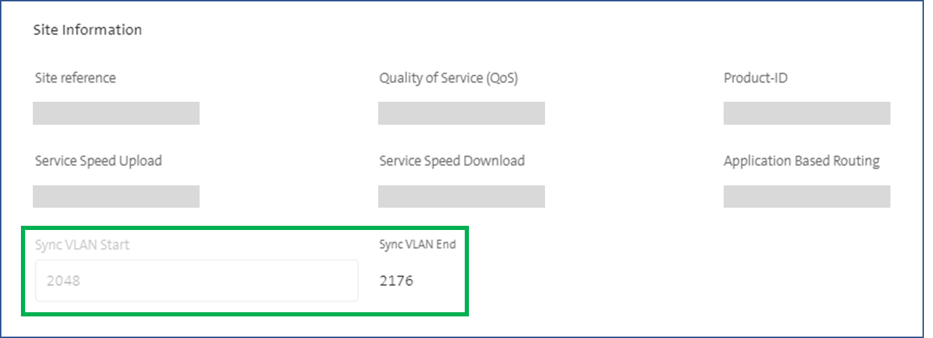
The VLAN-IDs used for the Ethernet connection can be seen in the EC Dashboard (see figure below) and must be transmitted transparently between the routers. However, you can change these sync VLAN-IDs before the first activation of the site. Should you need to change the sync VLAN IDs, the site first has to be deactivated. After this, you can redefine the sync VLAN-IDs and reactivate the site. However, a ZTP is then required again.
-
At least 13 VLAN IDs must be configured on both Ethernet connections
-
Both connections are Ethernet trunks and use identical VLAN IDs. Please take note that both connections have to run via separate paths. The ports GE6 and GE7 from AR657W, the 10GE ports 10 and 11 from AR6280 and the 10G-ports 6 and 7 from AR8140 may not be connected with each other via layer 2.
-
Please ensure you configure your switch ports to which you connect the router exclusively with the "Sync VLAN-IDs" according to the Dashboard (see figure below). The configuration of other VLAN IDs can result in loops and result in port shut-downs. The result of this is that redundancy cannot be guaranteed.
-
The Ethernet connections must support at least an MTU of 1996 bytes.
-
The bandwidth on the Ethernet connection must be designed for the maximum bandwidth of the Ethernet interface used by the router (1Gbps or 10Gbps)
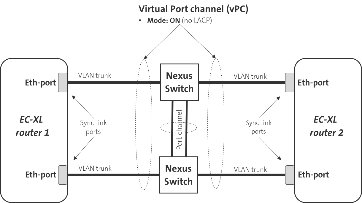
Implementation Example: Sync-Links via Cisco Nexus Switches
As an example, the following figure shows how a Cisco Nexus infrastructure must be configured so that the two sync link connections can be created.
This example also acts as reference for the implementation with other networking vendors. Of course, Swisscom also offers additional services that support you in configuring your infrastructure.
To ensure high availability of EC-XL, the two Ethernet connections must also be routed via two Nexus switches. If one Nexus switch fails, the connection via the second Nexus switch remains available. A virtual port channel (vPC) must be configured on both Nexus switches to connect both Ethernet ports of the EC-XL routers.
The channel mode for vPC must be configured to ON. LACP mode is not supported by the EC-XL routers.
To ensure high availability here too, two connections with port channels should also be used between the Nexus switches. If a connection between the Nexus switches fails, the connectivity between the Nexus switches still remains available.
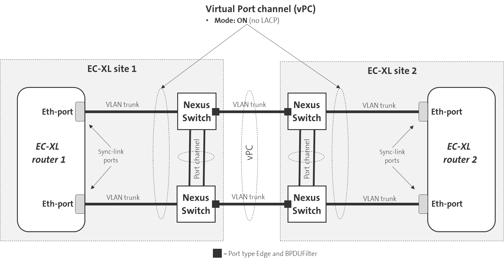
Router connection between two sites
The EC-XL routers can also be installed in different sites/locations.
In the case of the EC-XL order, two different router sites were also stated.
Two different router sites are then also accordingly displayed in the Dashboard.
Following the example above, the two Ethernet connections must also be connected through two Cisco Nexus switches at each site. In case of a failure of one Nexus switch, the connection through the second Nexus switch will still be available. A virtual port channel (vPC) must be configured on both Nexus switches at each site to connect both Ethernet ports of the EC-XL routers.
The channel mode for vPC must be configured to ON. LACP mode is not supported by the EC-XL routers.
Two connections with port channels should also be used between the Nexus switches at each site to ensure high availability here as well. If a connection between the Nexus switches fails, connectivity between the Nexus switches will still be available.
A virtual port channel must also be configured between the Nexus switches present at the two sites. The Ethernet ports at the two sites connecting the Nexus switches together must be configured as EDGE ports and BPUFilter must be configured.
Setup of EC-XL without sync link (active-passive)
In EC-XL without sync link, the WAN links are in an active-passive mode, so data traffic is transmitted only over one link at a time, while the other link acts as a backup. In this setup the routers do not have to be directly interconnected, allowing for more flexibility in the deployment.
Dual-gateways without sync-link can be deployed using two LAN routing configurations:
- VRRP-based setups where the failover from the active to the passive CPE is done using the VRRP protocol.
- eBGP routing options where prefixes and AS-path adjustments manage traffic prioritization in case of failover.
Setup redundancy using VRRP
The following prerequisites have to be met:
- The routers have to be interconnected on layer 2.
- This can be achieved either through a local switching infrastructure or direct Ethernet links.
- A VPN is already assigned to the EC-XL site.
To configure redundancy using VRRP, follow these steps:
- Create a campus wide VLAN on both CPEs for the local LAN subnet. This automatically establishes an infrastructure BGP peering between both routers. For more information regarding VLAN configuration, please visit this page: VLANs and LAN-IP addressing
- Enable VRRP and define a VRRP IP to use as gateway. For more information about configuration of VRRP, see: Configuring VRRP
Setup in BGP mode
The following prerequisites have to be met:
- The LAN routers support BGP
- A VPN is already assigned to the EC-XL site.
An interconnection between the routers on layer 2 or layer 3 is optional.
To configure redundancy using BGP, follow these steps:
- Configure a VLAN on each CPE to use as transit subnet towards the LAN side routers
- Go to the routing tab and add a BGP peer for each VLAN created before. For more information see: Configure BGP
- Configure the LAN side routers to establish an external BGP peering to the EC-XL router
- Configure the LAN side routers to the individual requirements of the network design.
It is also possible to setup active-passive redundancy using a combination of VRRP and BGP.
Modify Active/Standby CPE Configuration
To switch the active and standby CPE via the dashboard, please follow the detailed steps below:
- Navigate to Locations > Enterprise Connect.
- Under CPE selection, review the currently configured active and standby CPEs.
- To switch the active/standby designation, select the desired CPE from the Choose Active CPE selection menu.
- Click Save to apply the changes and update the configuration.
Connecting customer switches to EC-XL
All EC-XL routers have an internal layer 2 switch.
For information, the following parameters are configured on this internal switch and cannot be changed:
-
Multiple Spanning Tree (MSTP) is enabled by default
-
Bridge priority: 32,768
-
Port priority: 128
-
Forward delay time: 15 seconds
-
Hello time: 2 seconds
-
Max. age time: 20 seconds
If two or more switches are connected to both EC-XL devices, then they must be configured the following way:
-
Multiple Spanning Tree (MSTP) or Rapid Spanning Tree must be enabled
-
Spanning tree port type set to NORMAL
-
Check that BPDU filters are disabled
-
Check that BPDU guard is disabled
-
Recommendation: Bridge priority less than 32,768
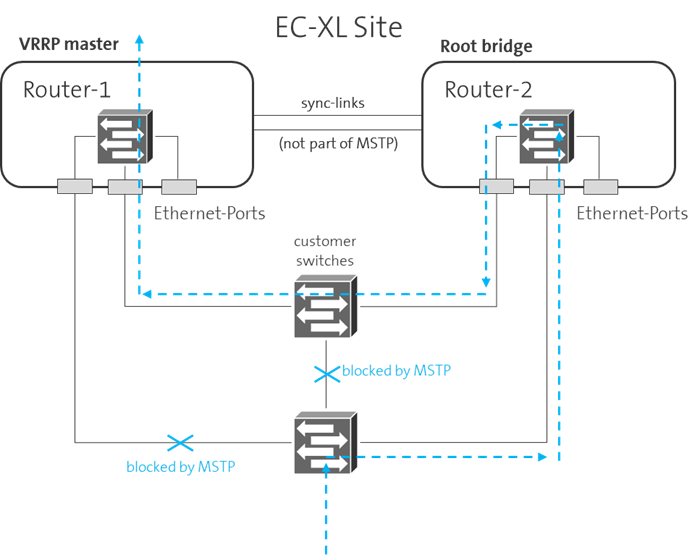
It is recommended that the EC-XL-devices should not be elected as a root bridge from the spanning tree protocol. Therefore the bridge priority value at the customer switches should be less than 32'768.
This is not a must, but if the root bridge function is on a EC-XL device and the same device is not VRRP master, then the optimal, shortest path through the Layer 2 network towards the WAN cannot be guaranteed for certain data streams (see figure below as example)
For optimal redundancy with routers AR8140 or AR6280, it's recommended to connect customer equipment using a Link Aggregation Group (LAG). This setup enhances reliability by combining multiple connections into a single logical link. For detailed configuration instructions, refer to the Setup Router Ports documentation.
EC-XL Redundancy test
An EC-L site has redundant connections to the EC-XL network (WAN) and to the LAN for providing 99.99% availability. If a WAN or/and a LAN port is interrupted, the connection to other sites and thus the WAN service must continue to function.
Please check this by performing the following tests.
The prerequisite is that the WAN service has already been correctly
configured on the routers via EC Dashboard.
-
WAN redundancy test:
Interrupt one of the two WAN connections one after the other, that means at least one WAN connection always remains active.
A maximum service interruption of approx. 30 seconds can be the result. -
LAN redundancy test:
Interrupt one of the two LAN connections one after the other, that means at least one LAN connection always remains active.
If the redundancy is configured based on VRRP, then the service interruption should only be a few seconds. If the LAN redundancy is based on BGP, then the convergence time depends on the configured BGP parameters. -
Test the sync links (if EC-XL with sync link):
Interrupt the WAN port of the VRRP master router. After the WAN service is working again, interrupt one of the two sync links in turn. Please note that at least one sync link must always be active. The WAN service should not be interrupted.
The EC-XL redundancy test can be considered successful if the WAN service has always worked during all the above-mentioned connection interruptions.
The EC-XL redundancy test must always be repeated if a major change (configuration) has been made on the LAN side or in your applications.